WEATHERCLOCK SCHEMATIC
ESP32-S3 Super Mini + GC9A01 Display + AHT20/BMP280 Sensor + LEDs + Charging Module
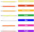
PIN CONNECTIONS
| COMPONENT | COMPONENT PIN | ESP32-S3 PIN | WIRE COLOR |
|---|---|---|---|
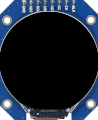
| GC9A01 Display | VCC | 3V3 | Red |
| GND | GND | Black | |
| CS | GPIO 12 | Green | |
| DC | GPIO 11 | Orange | |
| RST | GPIO 10 | Purple | |
| SDA/MOSI | GPIO 9 | Cyan | |
| SCL/SCLK | GPIO 8 | Yellow | |
| BL | GPIO 13 | White | |
| AHT20+BMP280 Sensor | VCC | 3V3 | Red |
| GND | GND | Black | |
| SDA | GPIO 7 | Cyan | |
| SCL | GPIO 6 | Yellow | |
| LEDs (x4) | LED1 Anode (0-14s) | GPIO 5 | Red |
| LED2 Anode (15-29s) | GPIO 4 | Green | |
| LED3 Anode (30-44s) | GPIO 3 | Blue | |
| LED4 Anode (45-59s) | GPIO 2 | Yellow | |
| All LED Cathodes | Cathode (-) | GND | Black |
| TP4056 Charger | OUT+ | ESP32 5V | Red |
| OUT- | ESP32 GND | Black | |
| B+ | Battery (+) | Red | |
| B- | Power Switch OUT | Black | |
| Power Switch | IN (right) | Battery (-) | Black |
| OUT (left) | TP4056 B- | Black | |
| 18650 Batteries (x2) | Positive (+) [Parallel] | TP4056 B+ | Red |
| Negative (-) [Parallel] | Power Switch IN | Black |
IMPORTANT NOTES
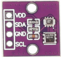
- I2C Addresses: AHT20 = 0x38, BMP280 = 0x77
- LEDs: Active HIGH (GPIO HIGH = LED ON). If using LEDs with built-in resistors, no external resistor needed. If using bare LEDs, add a 220-330 ohm resistor in series with each LED to limit current.
- Display: Uses software SPI. No MISO connection needed (write-only). Pins at bottom of display.
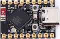
- 5V Input: The TP4056 OUT+ provides ~4.2V (fully charged) to ~3.0V (discharged) from the batteries. This connects to the ESP32's 5V pin, which feeds the onboard voltage regulator. Despite the name "5V", the ESP32-S3 accepts 4.0-6.0V on this pin.
- 3.3V Output: The ESP32's internal LDO regulator converts the 5V input down to 3.3V. This 3.3V rail powers all external components (display, sensor, LEDs). Never connect 5V directly to components - they require 3.3V!
- Power Switch: Located on the battery NEGATIVE rail between the 18650s and TP4056 B- pin. Placing the switch on the negative rail is safer - it completely isolates the batteries when OFF, preventing any current flow. Turn OFF before connecting USB to charge safely, as this prevents back-feeding the batteries during charging.
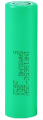
- Batteries: Two 18650 cells wired in PARALLEL (3.7V nominal, doubled capacity). Connect to TP4056 B+ and B- pins.
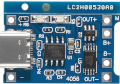
- Charging: TP4056 charges batteries via USB-C. Red LED = charging, Green LED = full.
- LED Behavior: All 4 LEDs stay ON, one blinks every 500ms to show current 15-second interval
- Ground: All GND pins connect to common ground rail (ESP32 GND, sensor GND, display GND, LED cathodes)