ALIVE SERVER MONITOR

ESP32-S3 Super Mini + GC9A01 Display + Status LEDs

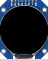
GC9A01 1.28 inch Round LCD Display

GC9A01 ROUND LCD

1.28" 240x240 SPI Display

VIEW ON AMAZON
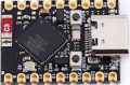
ESP32-S3 Super Mini

ESP32-S3 SUPER MINI

Main Microcontroller

VIEW ON AMAZON
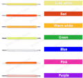
5mm LEDs Multi-Color

5mm LEDs (BLUE/RED)

Status Indicator LEDs

VIEW ON ALIEXPRESS
ESP32-S3 Super Mini USB-C TX RX 1 2 3 4 5 6 7 5V GND 3.3V 13 12 11 10 9 8 GC9A01 Display GND VCC SCL SDA RES DC CS BLK ALIVE 240x240 OK + - BLUE (G5) All Servers OK ALERT + - RED (G4) Server Down TP4056 Charger USB-C OUT+ B+ B- OUT- 18650 Batteries (x2) (Parallel) 3.7V + - 3.7V SWITCH OUT IN 5V IN Wire Colors 5V Power (to ESP32) Ground (GND) SPI CLK (G8) SPI MOSI (G9) Blue LED (G5) Red LED (G4)

LED INDICATOR BEHAVIOR

BLUE LED RED LED MEANING
ON (Always) OFF All servers responding - System Healthy
ON (Always) FLASHING (500ms) One or more servers not responding - ALERT

PIN CONNECTIONS

COMPONENT COMPONENT PIN ESP32-S3 PIN WIRE COLOR
GC9A01 Display VCC 3V3 Red
GND GND Black
CS GPIO 12 Green
DC GPIO 11 Orange
RST GPIO 10 Purple
SDA/MOSI GPIO 9 Cyan
SCL/SCLK GPIO 8 Yellow
BL (Backlight) GPIO 13 White
Status LEDs Blue LED Anode (+) GPIO 5 Blue
Red LED Anode (+) GPIO 4 Red
LED Cathodes Cathode (-) via 330R GND Black
TP4056 Charger OUT+ ESP32 5V Red
OUT- ESP32 GND Black
B+ Battery (+) Red
B- Power Switch OUT Black
Power Switch IN Battery (-) Black
OUT TP4056 B- Black
18650 Batteries (x2) Positive (+) [Parallel] TP4056 B+ Red
Negative (-) [Parallel] Power Switch IN Black

IMPORTANT NOTES

  • Display: Uses software SPI. No MISO connection needed (write-only). Same pinout as WeatherClock project.
  • LEDs: Active HIGH (GPIO HIGH = LED ON). If using LEDs with built-in resistors, omit the 330 ohm resistors.
  • Ping Library: Install ESP32Ping library via Arduino Library Manager.
  • 5V Input: The TP4056 OUT+ provides ~4.2V (fully charged) to ~3.0V (discharged) from the batteries. This connects to the ESP32's 5V pin, which feeds the onboard voltage regulator. Despite the name "5V", the ESP32-S3 accepts 4.0-6.0V on this pin.
  • 3.3V Output: The ESP32's internal LDO regulator converts the 5V input down to 3.3V. This 3.3V rail powers all external components (display, LEDs). Never connect 5V directly to components - they require 3.3V!
  • Power Switch: Located on the battery NEGATIVE rail between the 18650s and TP4056 B- pin. Placing the switch on the negative rail is safer - it completely isolates the batteries when OFF, preventing any current flow. Turn OFF before connecting USB to charge safely, as this prevents back-feeding the batteries during charging.
  • Batteries: Two 18650 cells wired in PARALLEL (3.7V nominal, doubled capacity). Connect to TP4056 B+ and B- pins.
  • Charging: TP4056 charges batteries via USB-C. Red LED = charging, Green LED = full.
  • Check Interval: Servers are pinged every 30 seconds (configurable in code).
  • WiFi Reconnect: Automatically reconnects if WiFi connection is lost.
  • Server List: Edit the servers[] array in code to add your own IP addresses or hostnames.